M31/M33XX digitizers are part of the new M3XXXA family of FPGA-programmable AWGs and digitizers. These high-performance digitizers with high channel density (up to 8 Ch in a single 3U PXIe slot) have an advanced data acquisition system (DAQ), includes easy-to-use programming libraries (section 3.1.1.1) and provides optional real-time sequencing and decision making capability (Hard Virtual Instrumentation or HVI: section 3.1.2.1) with precise timing and multi-module synchronization. Graphical FPGA programing (section 3.1.2.2) allows for FPGA customization without HDL programming expertise and performance penalty.
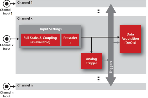
The M31/M33xx Digitizers has a flexible and powerful input structure to acquire signals (Figure 1).
Figure 1: M31/M33XXA Digitizers input functional block diagram. All input channels have identical structure.
Figure 1 shows Keysight standards for the output labeling (channel enumeration starts with CH1), however function open (Section 2.4.2.1) provides a compatibility mode for legacy modules (channel enumeration starts with CH0).
Modules are opened by default with the enumeration mode of its front panel. However, it is possible to open them in compatibility mode, forcing enumeration to the selected option. This option might be needed when different modules coexist.
The compatibility options are shown in Table 0.
Output Signal Selection
| Programming Definitions | |||
|---|---|---|---|
| Option | Description | Name | Value |
| Legacy | Channel enumeration starts with CH0 | COMPATIBILITY_LEGACY | 0 |
| Keysight | Channel enumeration starts with CH1 | COMPATIBILITY_KEYSIGHT | 1 |
Table 0: Compatibility, Section 2.4.2.1)
The M31/M33XXA Digitizers provides a block that allows the user to configure all the input settings such as input impedance, full scale, coupling, prescaler, etc.
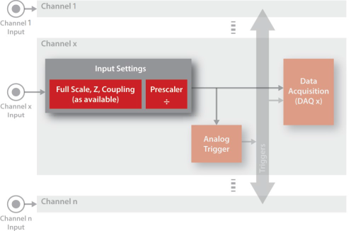
Figure 2: Input settings in the M31/M33XXA Digitizers functional block diagram
Depending on the product specifications the user can configure the input full scale value, the input impedance (Table 1) and the input coupling (Table 2). The full scale parameter adjusts automatically the input gain to maximize the input dynamic range.
Product-dependent Settings: This Section describes all the possible input settings, but in reality they are product-dependent. Please check the corresponding product datasheet to see if they are applicable.
| Programming Definitions | |||
|---|---|---|---|
|
Option |
Description |
Name |
Value |
|
High Impedance |
Input impedance is high (value is product dependent, check the corresponding datasheet) |
AIN_IMPEDANCE_HZ |
0 |
|
50Ω |
Input impedance is 50Ω |
AIN_IMPEDANCE_50 |
1 |
Table 1: Options for the input impedance setting (parameter impedance in function channelInputConfig.
| Programming Definitions | |||
|---|---|---|---|
|
Option |
Description |
Name |
Value |
|
DC |
DC coupling |
AIN_COUPLING_DC |
0 |
|
AC |
AC coupling |
AIN_COUPLING_AC |
1 |
Table 2: Options for the input coupling setting (parameter coupling in function channelInputConfig.
| Function Name | Comments | Details |
|---|---|---|
| channelInputConfigIt | configures the input full scale, impedance and coupling settings | Section 2.3.4.1 on page 28 |
Table 3: Programming functions related to the input full scale, impedance and coupling settings
The prescaler is used to reduce the effective input sampling rate, capturing 1 out of n samples and discarding the rest. The resulting sampling rate is as follows:

where:
 is final effective sampling frequency
 is the Clock System
  is an integer value (4 bits)
|
Function Name |
Comments |
Details |
|---|---|---|
|
channelPrescalerConfig |
It configures the input prescaler |
Table 4: Programming functions related to the input prescaler
The analog trigger block processes the input data and generates a digital trigger that can be used by any Data Acquisition Block (Data Acquisition (DAQs)).
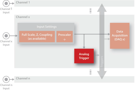
Figure 3: Analog trigger processor in the M31/M33XXA Digitizers functional block diagram
The user can select the threshold and the trigger mode. The available trigger modes are shown in Table 5.
|
Option |
Description |
Name |
Value |
|---|---|---|---|
|
Rising Edge |
Trigger is generated when the input signal is rising and crosses the threshold |
AIN_RISING_EDGE |
1 |
|
Falling Edge |
Trigger is generated when the input signal is falling and crosses the threshold |
AIN_FALLING_EDGE |
2 |
|
Both Edges |
Trigger is generated when the input signal crosses the threshold, no matter if it is rising or falling |
AIN_BOTH_EDGES |
3 |
Table 5: Options for the analog trigger (parameter analogTriggerMode in function channelTriggerConfig
|
Function Name |
Comments |
Details |
|---|---|---|
|
channelTriggerConfig |
It configures the analog trigger for each channel |
Table 6: Programming functions related to the analog triggers
The Data Acquisition (DAQ) is a powerful and flexible block which acquires incoming words and sends them to the user PC using dedicated DMA channels (Figure 5).
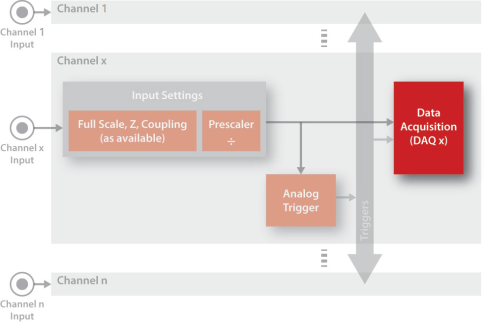
Figure 4: DAQ units in the M31/M33XXA Digitizers
The words acquisition requires two easy steps:
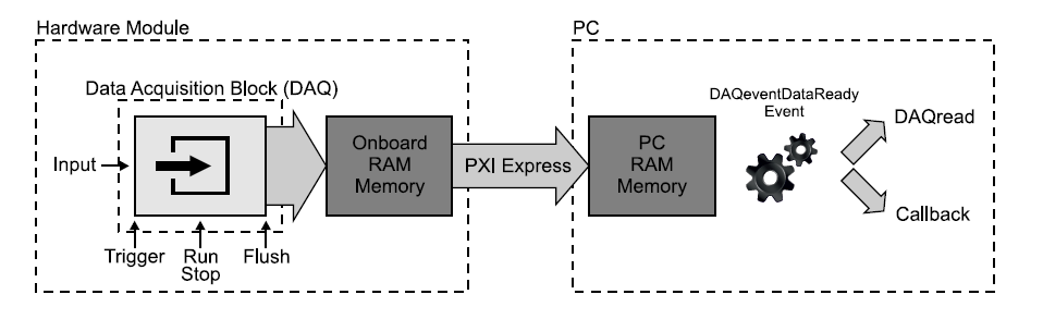
Figure 5: M31/M33XXA Digitizers words acquisition operation
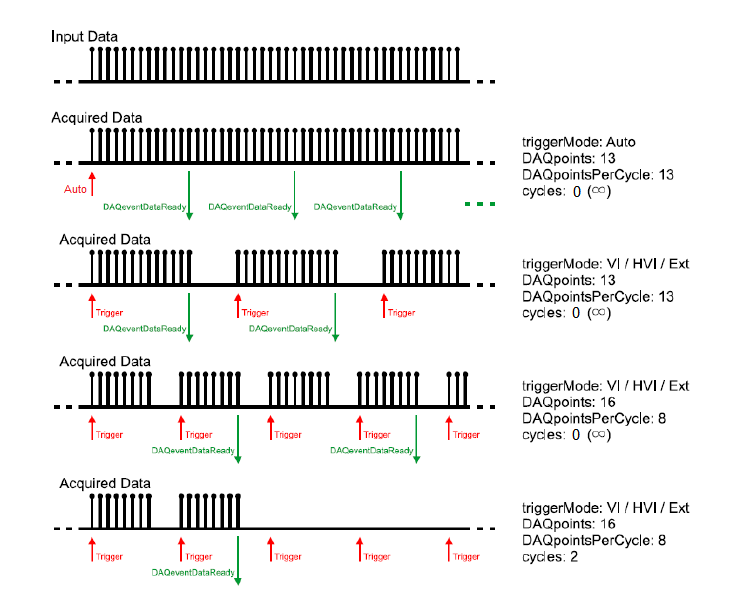
Figure 6: Examples of the DAQ operation (not all trigger methods are available in all modules)
Prescaler: The DAQ block has an input prescaler which can be configured to discard words, reducing the effective acquisition data rate (function DAQconfig).
DAQ counter: The DAQ block has a dedicated counter to store the number of acquired words since the last call to DAQconfig or DAQflush. This counter can be read with DAQcounterRead.
As previously explained, the user can configure the trigger for the acquisition. The available trigger modes for the DAQ are show in Table 7).
| Programming Definitions | |||
|---|---|---|---|
| Option | Description | Name | Value |
| Auto (Immediate) | The acquisition starts automatically after a call to function DAQstart | AUTOTRIG | 0 |
| Software / HVI | Software trigger. The acquisition is triggered by the function DAQtrigger, DAQtrigger provided that the DAQ is running. DAQtrigger can be executed from the user application (VI) or from an HVI (see HVI details, HVI Programming Overview) | SWHVITRIG1 | 1 |
| Hardware Digital Trigger | Hardware trigger. The DAQ waits for an external digital trigger | HWDIGTRIG | 2 |
| Hardware Analog Trigger | Hardware trigger. The DAQ waits for an external analog trigger (only products with analog inputs) | HWANATRIG | 3 |
Table 7: DAQ trigger modes (parameter triggerMode in function DAQconfig, Section 2.4.5.4 )
As show in Table 7, the user has the following options for hardware triggers:
| Option | Description | Name | Value |
|---|---|---|---|
| External I/O Trigger | The DAQ trigger is a TRG connector/line of the product (I/O Triggers). PXI form factor only: this trigger can be synchronized to CLK10, see Table | TRIG_EXTERNAL | 0 |
| PXI Trigger | PXI form factor only. The DAQ trigger is a PXI trigger line and it is synchronized to CLK10 | TRIG_PXI | 1 |
Table 8: External trigger source for the DAQ (parameter externalSource in function DAQdigitalTriggerConfig).
| Programming Definitions | |||
|---|---|---|---|
| Option | Description | Name | Value |
|
Active High |
Trigger is active when it is at level high |
TRIG_HIGH |
1 |
|
Active Low |
Trigger is active when it is at level Low |
TRIG_LOW |
2 |
|
Rising Edge |
Trigger is active on the rising edge |
TRIG_RISE |
3 |
|
Falling Edge |
Trigger is active on the falling edge |
TRIG_FALL |
4 |
Table 9: Hardware digital trigger behaviour for the DAQ (parameter triggerBehaviour in function DAQdigitalTriggerConfig)
| Function Name | Comments | Details |
|---|---|---|
| channelInputConfig | This function sets the input full scale, impedance and coupling | Section 2.4.5.1 |
| channelPrescalerConfig | This function configures the input | Section 2.4.5.2 |
| channelTriggerConfig | This function configures the analog trigger block for each channel | Section 2.4.5.3 |
| DAQconfig | This function configures the acquisition of words Data Acquisition (DAQs) | Section 2.4.5.4 |
| DAQdigitalTriggerConfig | This function configures the digital hardware triggers for the selected DAQ Trigger | Section 2.4.5.5 |
| DAQanalogTriggerConfig | This function configures the analog hardware trigger for the selected DAQ Trigger | Section 2.4.5.6 |
| DAQread | This function reads the words acquired with the selected DAQ Data Acquisition. It can be used only after calling the function DAQconfig and when a callback function is not configured | Section 2.4.5.7 |
| DAQstart | This function starts acquisition on the selected DAQ | Section 2.4.5.8 |
| DAQstartMultiple | This function starts acquisition on multiple DAQs | Section 2.4.5.9 |
| DAQstop | This function stops the words acquisition Data Acquisition of a DAQ | Section 2.4.5.10 |
| DAQstopMultiple | This function stops the words acquisition Data Acquisition of multiple DAQs | Section 2.4.5.11 |
| DAQpause | This function pauses the words acquisition Data Acquisition of a DAQs. Acquisition can be resumed using DAQresume. | Section 2.4.5.12 |
| DAQpauseMultiple | This function pauses the words acquisition Data Acquisition of multiple DAQs. Acquisition can be resumed using DAQresumeMultiple. | Section 2.4.5.13 |
| DAQresume | This function resumes acquisition on the selected DAQ Data Acquisition | Section 2.4.5.14 |
| DAQresumeMultiple | This function resumes acquisition on multiple DAQs Data Acquisition | Section 2.4.5.15 |
| DAQflush | This function flushes the acquisition buffers and resets the acquisition counter included in Data Acquisition block of a DAQ | Section 2.4.5.16 |
| DAQflushMultiple | This function flushes the acquisition buffers and resets the acquisition counter included in multiple Data Acquisition blocks of the DAQs | Section 2.4.5.17 |
| DAQtrigger | This function triggers the acquisition of words in the selected DAQ | Section 2.4.5.18 |
| DAQtriggerMultiple | This function triggers the acquisition of words in multiple DAQs | Section 2.4.5.19 |
| DAQcounterRead | This function reads the number of words acquired by the selected DAQ | Section 2.4.5.20 |
| triggerIOconfig | This function configures the trigger connector/line direction and synchronization/sampling method | Section 2.4.5.21 |
| triggerIOwrite | This function sets the trigger output. The trigger must be configured as output using function triggerIOconfig and I/O Triggers | Section 2.4.5.22 |
| triggerIOread | This function reads the trigger input | Section 2.4.5.23 |
| clockSetFrequency | This function sets the module clock frequency | Section 2.4.5.24 |
| clockGetFrequency | This function returns the real hardware clock frequency | Section 2.4.5.25 |
| clockGetSyncFrequency | This function returns the frequency of Clock System | Section 2.4.5.26 |
| clockResetPhase | This function sets the module in a sync state, waiting for the first trigger to reset the phase of the internal clocks CLKsync and CLKsys | Section 2.4.5.27 |
| DAQbufferPoolConfig | This function configures buffer pool that will be filled with the data of the channel to be transferred to PC. | Section 2.4.5.28 |
| DAQbufferAdd | Adds an additional buffer to the channel’s previously configured pool. | Section 2.4.5.29 |
| DAQbufferGet | Gets a filled buffer from the channel buffer pool. User has to call DAQbufferAdd with this buffer to tell the pool that the buffer can be used again. | Section 2.4.5.30 |
| DAQbufferPoolRelease | Releases the channel buffer pool and its resources. After this call, user has to call DAQbufferRemove consecutively to get all buffers back and release them. | Section 2.4.5.31 |
| DAQbufferRemove | Ask for a buffer to be removed from the channel buffer pool. If NULL pointer is returned, no more buffers remains in buffer pool. Returned buffer is a previously added buffer from user and user has to release/delete it. | Section 2.4.5.32 |
| FFT | Calculates the FFT of data captured by DAQread for the selected channel | Section 2.4.5.33 |
Table 10: Programming functions related to the digitizers